Development Process
Below is the development process for this project from the creation of texture maps to the final composited image
01.
Alpha Channel Table
Reading/ Writing
Texture Maps

RGB Table with top illumination
Reading and Writing Maps
02.
Shift from Perspective to Orthogonal Camera
The first step for this project was to allow the render to write texture maps for the pre-render pass. For the final render one needs access to an RGB and Alpha texture map for each slide of the virtual box created in the pre-render. However up until this point, my render only created and handled RGB based images, without an alpha channel. Therefore I needed to create functions to read and write these two channels (I have separated the two, RGB and Alpha, into their own images). In addition to the new function I had to change my code to support RGBA colors rather than the previous RGB vectors. The new alpha channel returns 1 if the camera intersects an object and 0 if it hits the background. With this, I will later be able to find what objects are hit within each slice.
Shift from Perspective to Orthogonal Camera
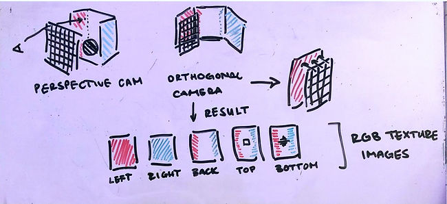
After establishing a way to read/write out texture maps, I had to change the type of camera to fit that of capturing a single wall or slice rather than the current perspective camera. To create virtual windows one must establish a virtual box of the room which is made up of slices parallel to each of the walls, and then any additional parallel to the window pane. In this step I am purely focusing on the walls for this trial. To appropriately capture this texture map, the camera must be orthogonal to the wall. In addition it is positioned slightly back from the wall to be able to capture all of the necesssary values. With this establoished, the camera will shoot rays perpendicular to the wall. The diagram above shows this shift in cameras and the resulting maps from this shift. I have created the test files for these instances, placing the orthogonal camera, denoted as "orthogonal" for now to test the different pixel processing process. The next step from this is relaying the wall's normal to the orthogonal camera to position itself rather than positioning it manually.


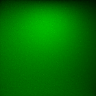
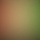
These are tester images of the orthogonal camera. As one can see, it is successfully reading in the rendered walls of the Cornell box, however there are still problems with the position of the pixels being shot from the camera and position of the camera plane. The rendered image is showing that of the marked box on the right, which indicates that the camera maybe too close and over center to the plane. However the accurate light glow on the back wall (left image) indicates that the scene is still rendering well despite the shift in camera types. This error will take minor debugging.


03.
Reading Textures and Mapping to Windows
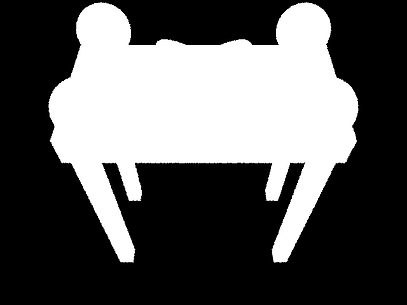
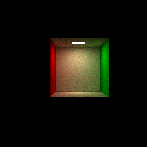
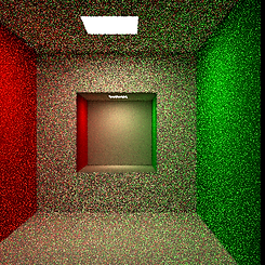
The images above show the final net of the Cornell Box using the orthogonal camera. These are the base images to check that the camera works. Later other slices from inside of the box will be added as textures using the same method.

Reading Textures and Mapping to Windows
To add the windows into the scene, I need to be able to map the texture image to the window. In order to do this, I first have to describe the window in terms of barycentric coordinates. Therefore, I created a new object type, textureTri, and defined vertices with their x, y, z location and u, v barycentric orientation. The image above shows the barycentric coordinates on the window.

Above shows that the image is correctly reading in and is placed at the right coordinates. However with textures you have to interpolate the neighboring pixels to find the color of the current pixel. As one can see the colors are incorrect in the mapping. And the image on the right shows this problem resolved.
04.
Window Placement Check

05.
Creating the Virtual Box
Window Placement Check
The image above shows the placement of the textures on each wall. This ensures that the textures and window objects are working appropriately.
Creating the Virtual Box
Now that the textures are working and mapping on to the walls properly, I can start focusing on slicing the virtual box. To do this I created a unit box of using the textures of the walls of the room. This will be my virtual room. With this I will be able to intersect a window, and transform the ray to hit this room and return a specific texture color.
06.
Rendering in the Virtual Box
01.
02.

03.

04.

Rendering in the Virtual Box
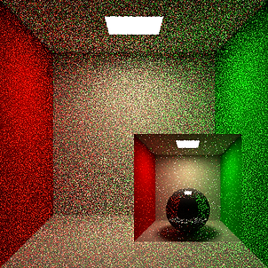
Finally I have connected the window object and the virtual room, or virtual box. When my program intersects a window it uses that point as the origin for the new ray it will shoot in the virtual room within my program. When a ray is shot in this room it intersects a texture and returns its color. Since it is tracing a ray in the virtual room it allows for the room to be three dimensional, as you can see by the camera moving. However since this room is just textures the program does not need to store more geometry to do this. In this stage however I am using the same ray direction in the box as the ray shot in our current room to test the intersection.
07.
Adding Rooms on Sides

Adding Rooms
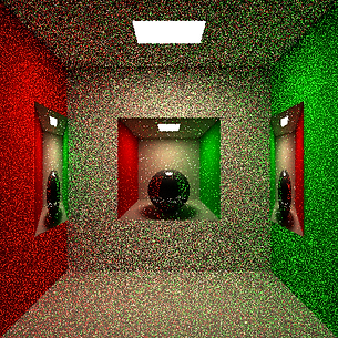
Now I have changed the ray direction of the ray in our virtual room to be transformed with the room. This allows for rooms at any angle to be rendered, not just a front facing room as before. In the image we can see that this allows for the rooms to go into the walls and they are themselves three dimensional.
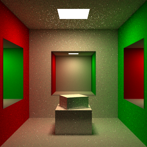
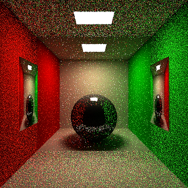
Furthermore, this is an image of the room with a statue in the middle and three empty display cases at 64 spp rather than the previous 1 spp.

Finally, here is the final product, Cornell Box with two side rooms and a 3 x 3 grid of display cases.
Further Improvements
08.
After completing this project, I would like to note some possible improvements. My implementation only slices the virtual box once after the walls due to rendering time. However with more time I would run the program with more slices, to get a smoother room transition through the windows.
Furthermore, it would be interesting to see the images produced by this project once it can read in .obj files. With this addition, the illusion of rooms would be more convincing.